The Luna Network HSM 7 is 1U high and fits into standard 483mm (19")-wide equipment racks.
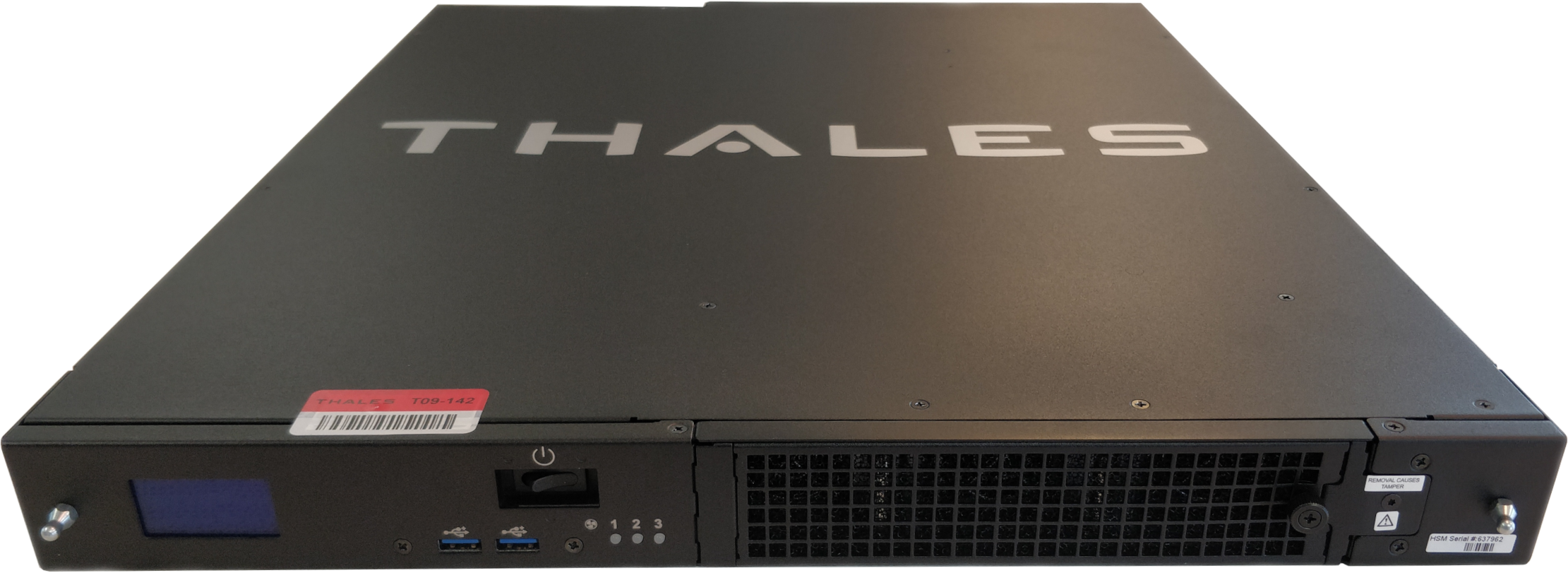
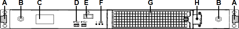
Front Panel
The front panel is illustrated below, with the secure locking bezel removed:
| Item | Name | Description |
|---|---|---|
| A | Front ear brackets | Connect to the front of the appliance chassis with the provided screws, allowing it to be mounted in a standard 483mm (19")-wide equipment rack. The extending tabs act as posts for the locking bezel. |
| B | Mounts for locking bezel | The secure locking bezel connects to the appliance faceplate here. |
| C | Front-panel display | Displays basic configuration and status information for the appliance. See also Front-panel LCD Display |
| D | USB 2.0 ports | The appliance has a total of four (4) USB 2.0 ports (two on the front panel and two on the back), for connecting to such devices as card readers and backup HSMs. |
| E | Start/stop switch | Powers the appliance on or off. See also Power-on, Power-off, or Reboot the Appliance. |
| F | Fan status LEDs | The appliance has three (3) cooling fans. If these lights are illuminated, the fans are working correctly. |
| G | Ventilation fan filter cover | Removable cover allows cleaning of air filter. See also Power Supply and Fan Maintenance. |
| H | Fan bay securing screw |
Torx screw secures the fan bay. CAUTION! Opening to swap fan modules triggers a tamper event on the appliance. See also Power Supply and Fan Maintenance. |
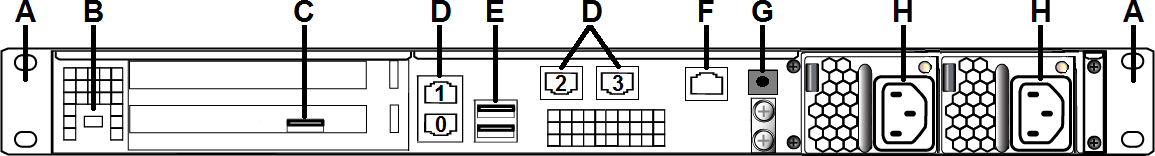
Rear Panel
The rear panel is illustrated below:
| Item | Name | Description |
|---|---|---|
| A | Sliding rail brackets | Connect to the sliding rails mounted on the sides of the appliance chassis, allowing it to be mounted in a standard 483mm (19")-wide appliance rack. |
| B | Kensington lock connector | Allows the appliance to be secured to a desk or equipment rack using a Kensington lock. |
| C | HSM card USB port |
When authenticating with a local Luna PED, the PED must be connected directly to the HSM card. NOTE This rule does not apply for multifactor quorum authentication to a Luna Backup HSM 7 connected to the appliance. In this case you connect a remote PED to one of the appliance USB ports and connect to the pedserver service running on the appliance at IP address 127.0.0.1. See Luna Backup HSM 7 Connected to Luna Network HSM 7 Using Luna PED for Multifactor Quorum Authentication for more information. |
| D | LAN ports |
The appliance has a total of four (4) 1Gbit LAN ports that can be bonded in active-backup mode. They are labeled on the illustration above as follows: >Bond0: eth0 and eth1 >Bond1: eth2 and eth3 |
| E | USB 2.0 ports | The appliance has a total of four (4) USB 2.0 ports (two on the front panel and two on the back), for connecting to such devices as card readers and backup HSMs. |
| F | RJ45 serial port | Connect a terminal to this port using the included RJ45 to USB cable (see Luna Network HSM 7 Required Items). See also Installing the Luna Network HSM 7 Hardware. |
| G | Decommission button | This button should only be pressed as part of decommissioning and zeroizing the appliance. See also Decommissioning the Luna Network HSM 7 Appliance. |
| H | Power supplies | Connect the appliance to power. For proper redundancy and best reliability, the power cables should connect to two completely independent power sources. See also Power Supply and Fan Maintenance. |
Luna Network HSM 7 Network Interface Configuration Variants
The configuration of the network interfaces on the Luna Network HSM 7 depends on the model, as follows:
>The 1G model provides four 1G RJ45 copper Ethernet network interfaces.
>The 10G model provides two 10G SFP optical Ethernet network interfaces, and two 1G RJ45 copper Ethernet network interfaces.
The mapping of the network interfaces to their software equivalents (eth0, eth1, eth2, and eth3) is different on each model, as detailed in the following sections. The network interface mappings are not configurable.
1G Model Network Interface Mapping
The 1G model provides four 1G RJ45 copper Ethernet network interfaces. You can optionally bond eth0 and eth1 to bond0, or eth2 and eth3 to bond1, to provide a redundant active/standby virtual interface.

10G Model Network Interface Mapping
The 10G-equpped Luna Network HSM 7 provides two 10G SFP optical Ethernet network interfaces (mapped to eth0/eth1), and two 1G copper RJ45 network interfaces (mapped to eth2/eth3). You can optionally bond eth0 and eth1 to bond0, or eth2 and eth3 to bond1, to provide a redundant active/standby virtual interface.
