Power Supply and Fan Maintenance
The two power supplies in the Luna Network HSM 7 appliance are hot-swap capable, meaning that one is sufficient to power the appliance while the other is removed and replaced, with no service interruption. The indicator light (LED) on each power supply shows different behavior, depending upon conditions.
| Power Supply Condition | Power Supply LED |
|---|---|
| DC present/only standby output on |
Flashing green (1Hz) |
| Power supply DC output ON and OK |
Steady green |
| Power supply failure |
Steady RED |
| Power supply warning |
Flashing Blue/Red (1Hz) alternating |
| Input power failure (only in n+1 configuration) |
Flashing Red (1Hz) |
A power supply controller in the appliance monitors the state of the power supplies. It ensures that a failed power supply still gets sufficient direct current from the remaining power supply to light the indicator LED. The controller also sounds an audible alarm when there is a problem, such as one power supply not being connected to AC main power.
If only one power supply is present, the audible alarm is silent. If you wish to operate your Luna Network HSM 7 appliance with only one power supply, we recommend that you remove the second supply to silence the audible alarm.
Replacing a Power Supply
You may need to replace a power supply in the event of a failure.
To remove a power supply
1.To remove a power supply, face the back of the appliance.
2.Disconnect/unplug the selected power supply.
3.Press the lever sideways to release the power supply retaining catch, and simultaneously pull the handle out toward you.
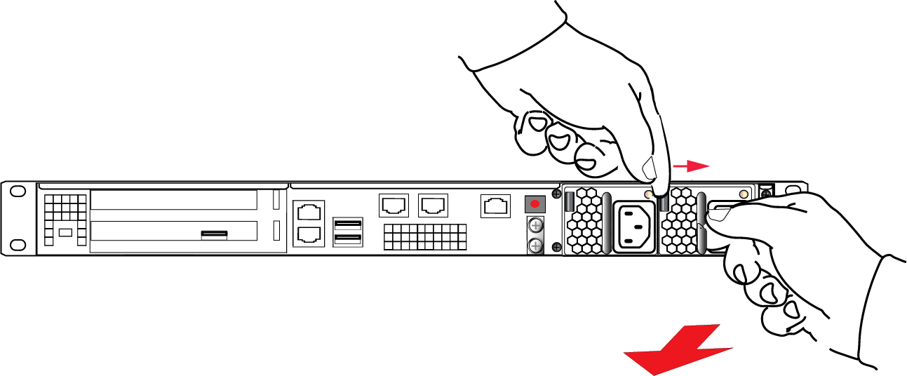
Withdraw the power supply completely, using your other hand to support the body of the power supply as it emerges.
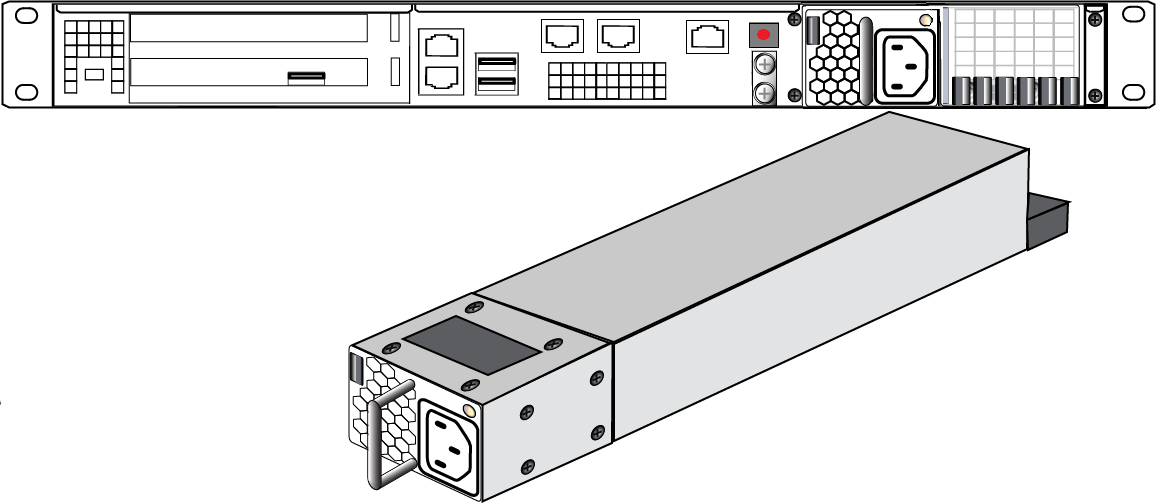
To re-install a power supply
1.To replace a power supply, reverse the steps above. Press firmly to seat the connector. The power supply can be fully inserted only in its proper orientation.
2.Connect an AC power cord.
The Fans
In normal operation, the fans should require no maintenance.
You might need to perform the following tasks:
>Clean the filter (occasionally)
>Replace a defective fan (rarely)
CAUTION! Opening the fan bay causes a system tamper event
We recommend that you use scheduled system maintenance downtime for this activity, as it will temporarily disrupt your client's access to your HSM partitions. If the system detects a tamper event, the HSM stops responding until you reboot (lunash:> sysconf appliance reboot), or until you use the Stop/Start switch on the appliance rear panel.
Cleaning the Filter
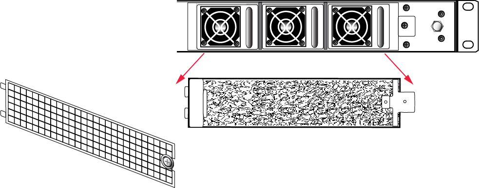
The ventilation grille, located to the right, on the appliance front panel, is secured in two parts, by two screws - a knurled, captive thumb-screw, and a Torx T8 screw. The knurled screw can be fastened or released without tools. It secures the lattice screen that in turn retains the mesh air filter.
While we recommend controlled-atmosphere environments for greatest longevity and reliability of the equipment, we recognize that some environments might include some dust in the air. The mesh filter traps larger particulate matter before it can be drawn into the interior of the appliance. In less-than-perfect non-clean-room conditions, the mesh might accumulate a buildup of dust, and should be cleaned occasionally for best cooling airflow into the equipment.
NOTE Accessing the air filter mesh in front of the fans (using the thumbscrew to open the retaining grille) does not cause a tamper.
To clean the filter
1.Twist the knurled knob counter-clockwise until it no longer secures the airflow lattice. The lattice is anchored at its left end by two tabs, and can be easily pulled off the appliance, once the knurled retaining screw is loosened.
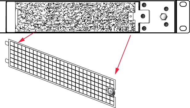
2.With the air filter exposed, it is easy to grasp the mesh with fingers and tug it free. The mesh is flexible and is held in its cavity only by friction. If it is dusty, handle carefully so as not to dislodge any dirt that could then be sucked in by the fans.
3.To clean the filter, either blow it out with compressed air (away from the vicinity of the appliance), or rinse with water. If using water, ensure that the mesh is dry before reinstalling.
4.To reinstall the mesh, place it in its cavity in front of the fans, and use fingers or a blunt tool to tuck-in the corners.
5.Then, replace the lattice in front of the mesh by inserting the tabs first, then swinging the lattice closed like a door, and securing with the knurled screw.
Replacing a Fan
The three fan modules (each containing two in-line fans) provide cooling redundancy. If one fan or module fails, it is detected by sensors. View a summary of appliance sensor conditions by running lunash:> status sensors. In the FAN section of the command output, the fans are listed in the order that they appear, left-to-right, as viewed from the front of the appliance. The example shows a fault with the first fan module:
----------- Front Cooling Fans Status --------------
FAN1A 	lnr 	0 RPM 	Unplugged or Failed
FAN1B 	lnr 	0 RPM 	Unplugged or Failed
FAN2A 	OK 	3000 RPM
FAN2B 	OK 	2900 RPM
FAN3A 	OK 	2900 RPM
FAN3B 	OK 	3000 RPM
When the system returns from restarting, the HSM returns to find both splits of the MTK available and it immediately reconstitutes the MTK, allowing you to resume operations.
NOTE Partition authentication data is de-cached by the tamper - you must re-activate each of your application partitions by logging in with the PED key and challenge secret before your clients can resume accessing them (see Activation on Multifactor Quorum-Authenticated Partitions). Partition activation does not survive a tamper event. In either case, you can examine the log for tamper events: lunash:> syslog tail -search tamper -entries 200
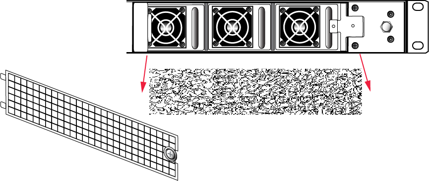
To replace a fan
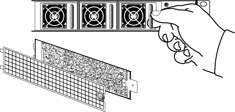
1.To open the fan bay, use a Torx number 8 screwdriver to remove the screw that secures the right-side tab of the fan retainer.

2.The fan retainer is anchored at its left by two tabs - swing the retainer out like a door, and remove it. There is no need to separate the filter mesh and its retainer from the larger fan retainer; the assembly can come out as one piece. The illustration below happens to show them separated.
3.The fan modules are now exposed and are held in place only by the friction of their electrical connectors.
4.Grasp the handle of the selected fan module and pull straight out toward you.
5.After slight initial resistance, the fan module should easily slide free of the appliance.
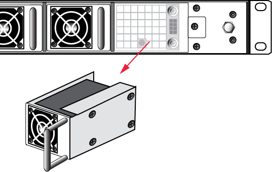
6.To replace the fan module or install a new one, reverse the above sequence.
The index peg on the back of the module, and the matching index hole at the back of the fan bay, ensure that the module can be inserted only in its proper orientation.
7.Close up, replace the bezel, reconnect any cables, and return the appliance to service. If the power was left on during the operation, you will nevertheless need to restart (lunash:> sysconf appliance reboot) in order to clear the tamper event caused by opening the fan bay.
8.You will also need to re-Activate your application partitions by logging in with the PED key and challenge secret before your clients can resume accessing them (see Activation on Multifactor Quorum-Authenticated Partitions).
Summary
Removing, cleaning, and replacing the fan filter (the black mesh behind the grille) does not cause a tamper, and can be done at any time without disrupting your Clients.
Opening the fan bay (behind the filter), by unscrewing that Torx screw, does cause a tamper and therefore some down-time for your Clients. If only one fan module is showing a defect, you can probably leave replacing it until scheduled down-time, during which there would be no unexpected disruption to your Clients.